Furnace Gas Flow Augmentation — XProject
August 2026 | University of Pittsburgh | Pennsylvania, United States of America
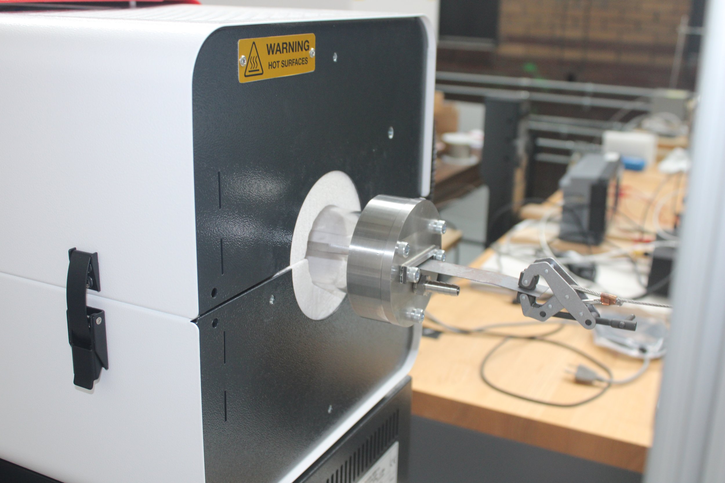
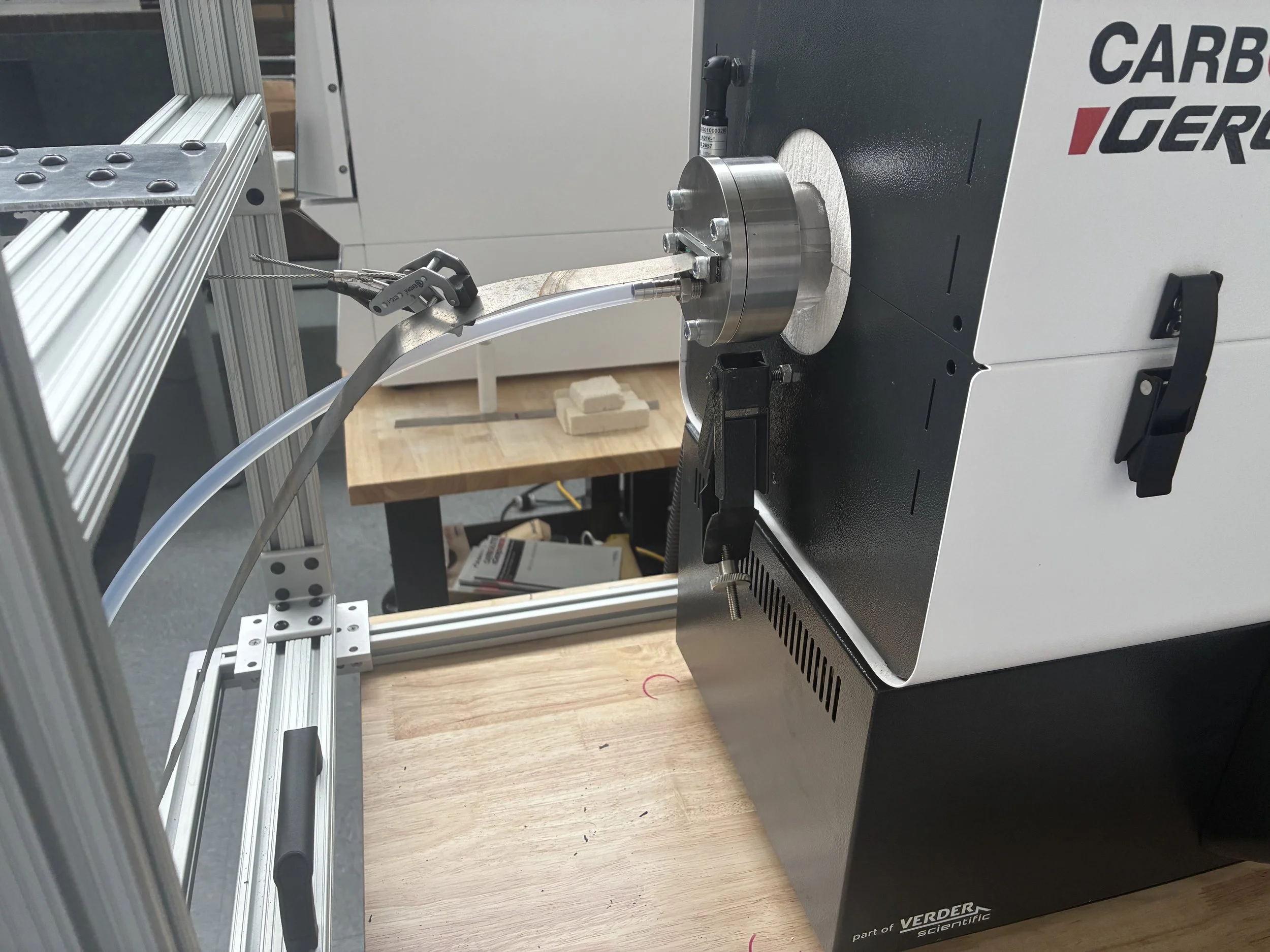
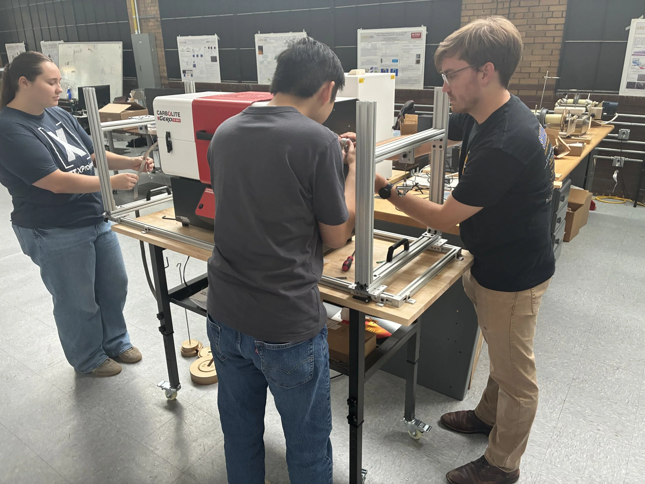
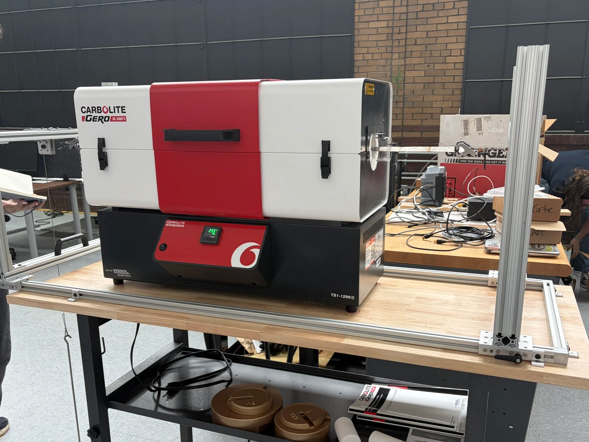
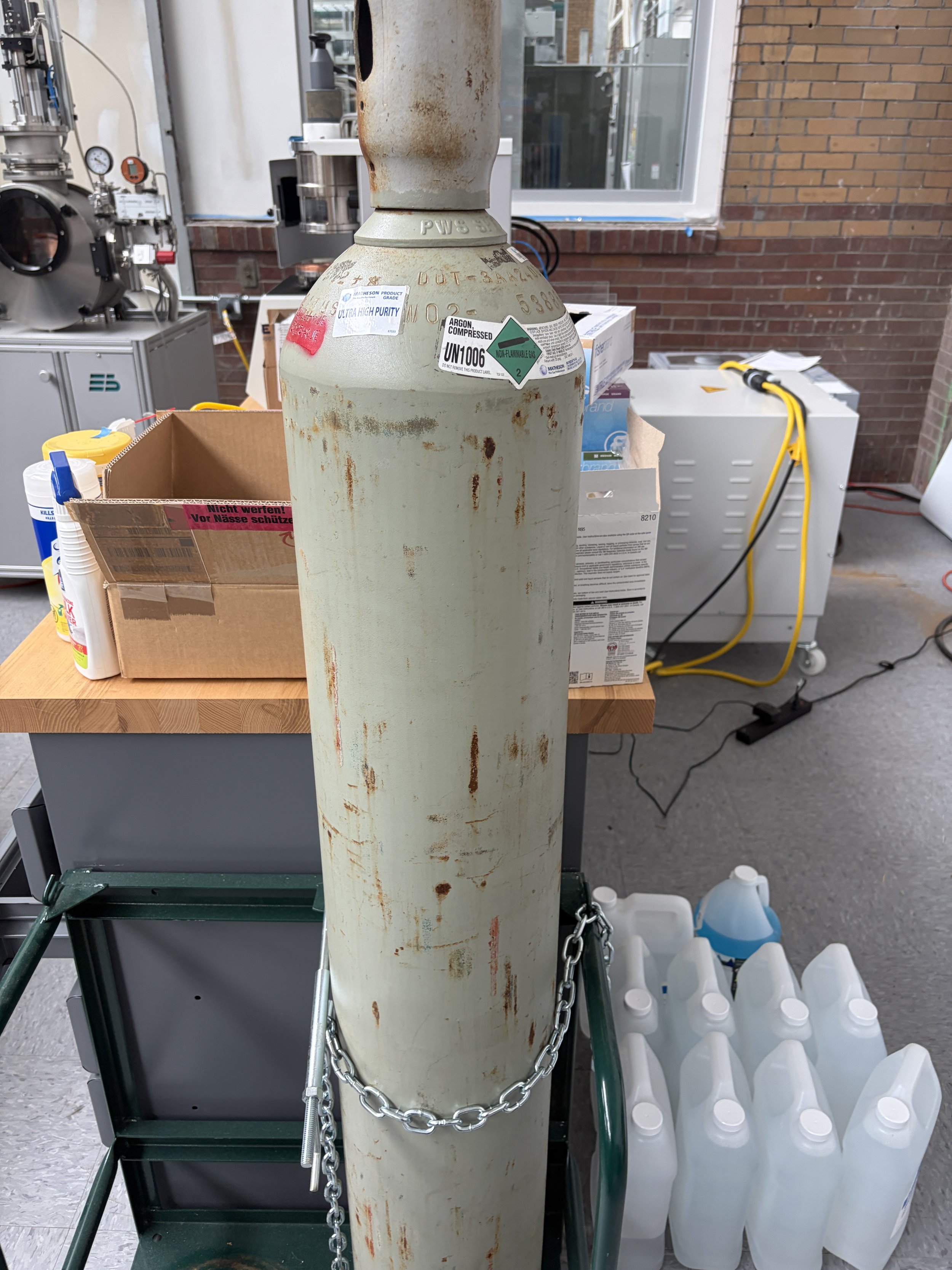
This project was a summer design project I worked on with the help of Pitt’s IDEA Lab. The objective of this project was to design end caps for a Carbolite tube furnace used by a graduate materials scientist at Pitt. The images below show that the furnace had the following attachments added: a tensioning system and an inert gas system. The tensioning system carried electrical strips for annealing in the furnace. Meanwhile, the inert gas system supplied compressed argon and nitrogen to blanket the electrical strips and prevent oxidation.
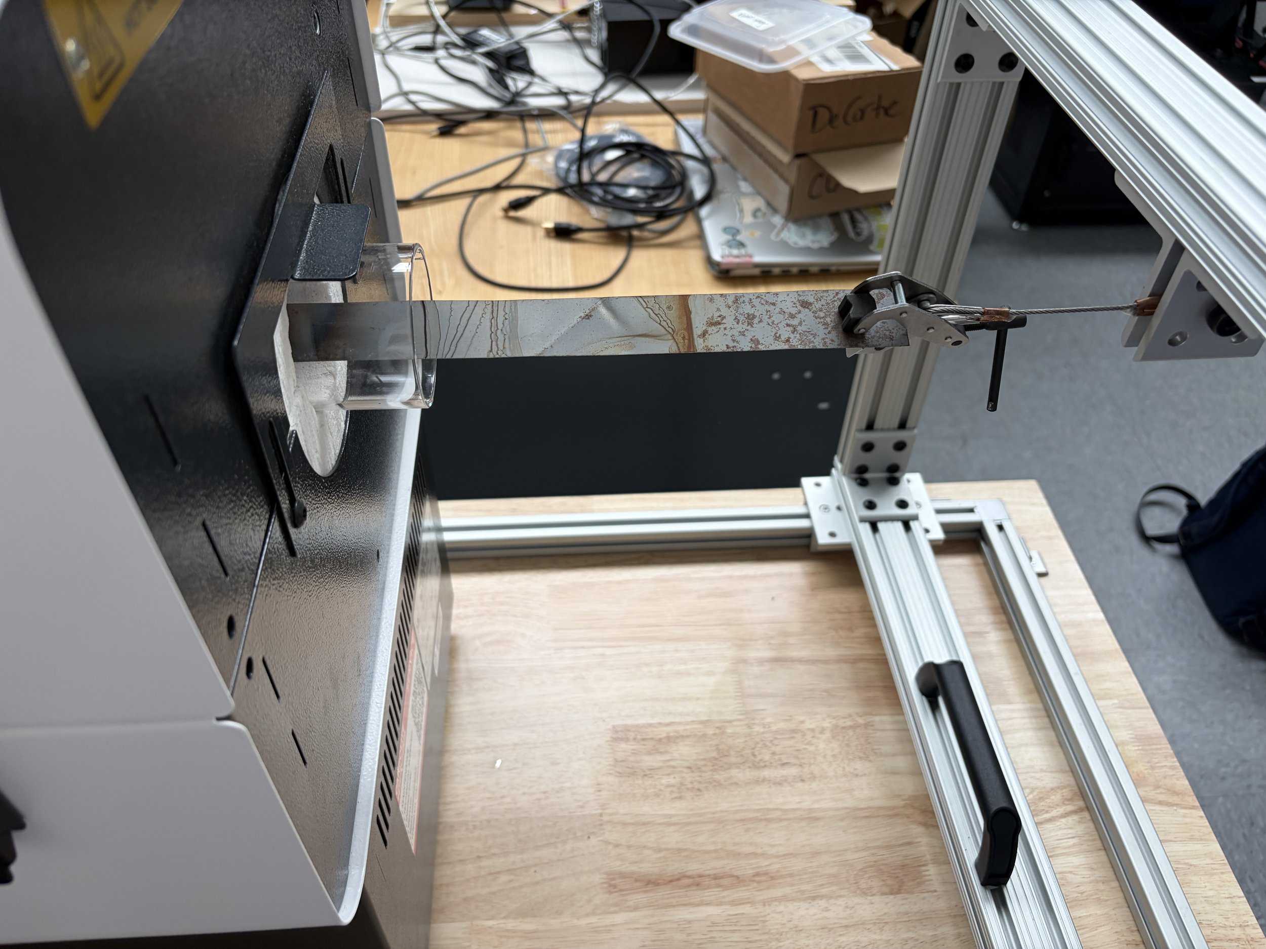
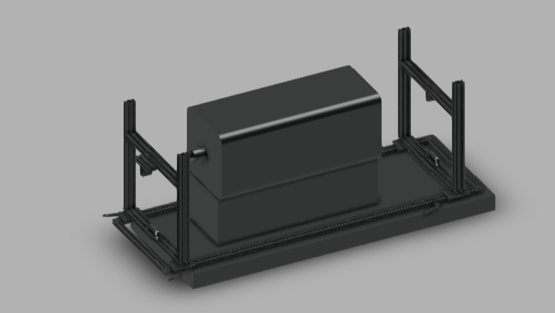
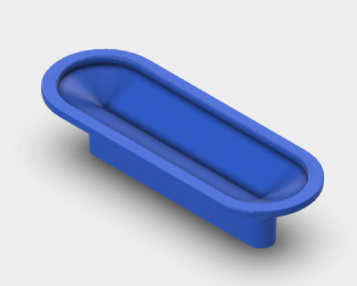
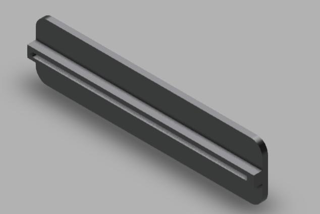
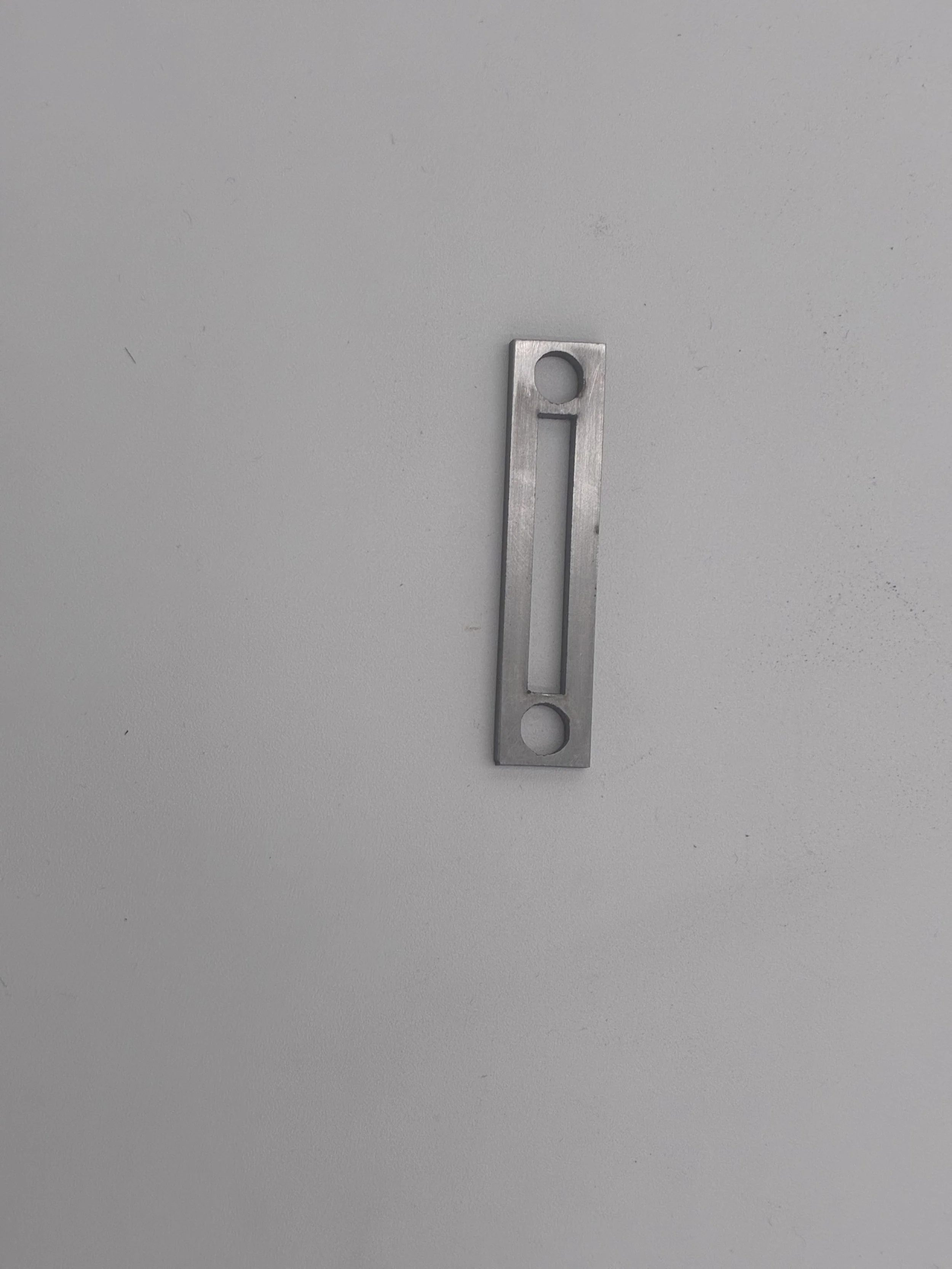
A major role I played in this project was to be one of the team’s designers. A major part of my work was designing slit inserts for the end caps, which would be new additions to the end caps we saw on other tube furnaces online. A major issue we tried to avoid when designing these end caps was gas leakage and tensioning issues in the strips. This is why, when trying to come up with different part iterations, we designers had to make sure that the slit would fit roughly the strip's thickness, 60mm, so that no air would escape the system. We had to keep in mind, though, that we should not make the slit hole the exact strip thickness, as the client stressed that the strips fed through may sometimes not be perfectly flat or straight. Additionally, doing this would minimize excessive tension when feeding the strip at both ends, which could cause it to snap given its thinness (thinner than paper).
During the design stages of the project, our team initially wanted to make the slit insert friction-fitted, as it seemed like the simplest option we could find (image of the model shown on the left). Though that seemed enticing, this may be problematic, as the insert's structural integrity could degrade over time due to exposure to extremely high temperatures and potential thermal expansion. Because of this, I thought: why not attach the insert, inside-out, to the seal using high-temperature adhesives (image of the model shown on the right)? This would ensure the insert could maintain its structural integrity and minimize tension throughout its use.
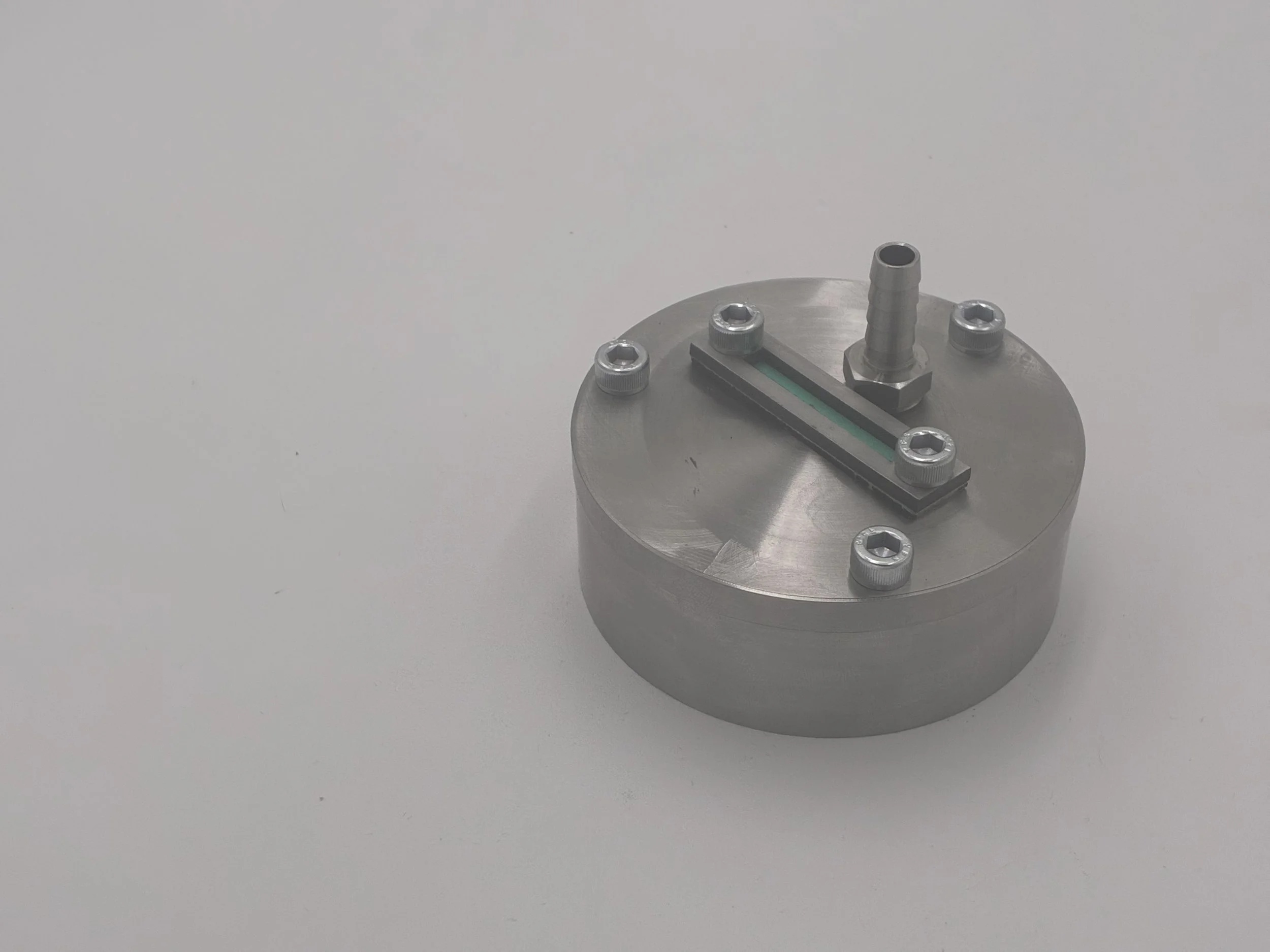
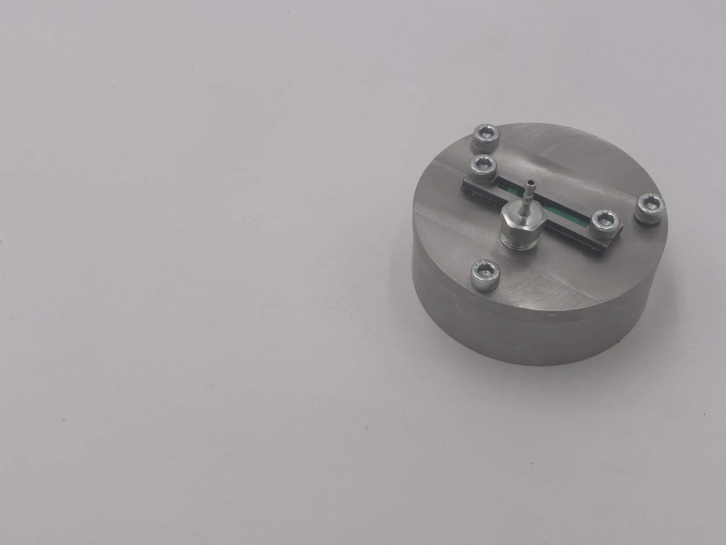
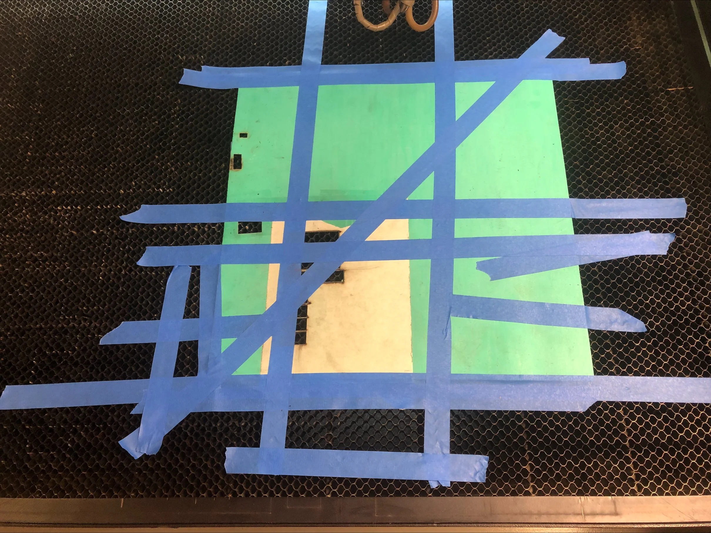
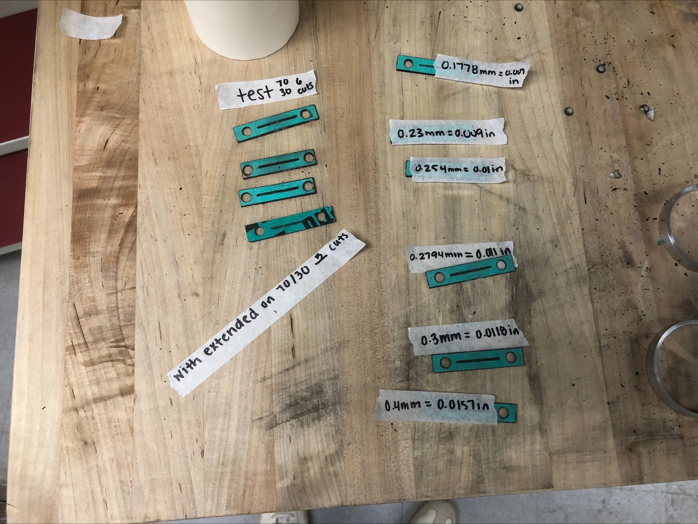
When finalizing our parts, the team integrated my design with slight modifications. As shown in the image in the first image below, instead of being attached inside-out with adhesive, it would be attached with screws and gaskets to ensure the utmost structural integrity. In line with this, another major responsibility I had was collaborating with the team to laser-cut gaskets from the purchased Buna-N material. This process was not straightforward, as we had to rely on trial and error to adjust the lasers' speed and intensity. Unlike the laser-cutting of wood commonly seen, Buna-N was harder to cut because it was much thicker than wood and would burn easily. Using the knowledge we had of laser cutters and some advice from our project supervisor, Ms. Amelia Gordon, we came up with the method of adding thick masking tape on both sides to avoid burns and regular masking tape on the edge to keep the material stable a shown in the second image. Fortunately, this worked, as shown in the last image, with no burns at the cut edges of the gaskets.
Photos of End Seals